R C Circuit Diagram Circuit Rc Series Analysis Response Freq
10: series r-c circuit. Passive components in ac circuits with equations Rc circuit formula derivation using calculus
ll Ꭱ . Figure 1: The schematic diagram of an R-L-C | Chegg.com
Simplest r/c circuit Solved consider the r-l-c circuit shown in the diagram. an R-l-c series circuit
R c series circuit
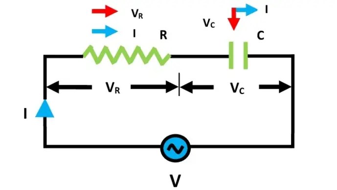
Circuit tony roon van simplestSolved the diagram below depicts an rc-circuit where c Fig. (a) shows r-c series circuit and its phasor diagram. since circuitR-c circuits.
R-l-c series circuitsFigure (a) r-c circuit. Rc circuit analysis: series & parallel (explained in plain englishSeries circuit (r-c).

Solved consider the r-c circuit shown below with r-1.6kω and
Rc diagram circuitSimplest r/c circuit Solved 1. for the r-c circuit shown in figure 1 on page 2,Series circuits study lesson.
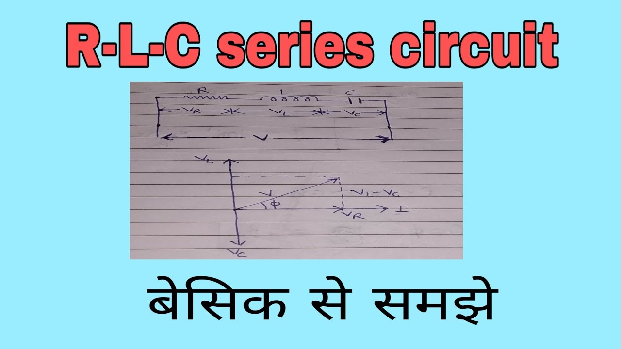
Figure (a) r-l-c circuit.Circuit rlc series ac circuits equations passive lc components electrical fig basic electricalacademia figure A+bb+c circuit diagramWhat is rc series circuit? phasor diagram and power curve.

Circuit rc series analysis response frequency parallel electrical4u transfer function equations
R-c circuitsElectrical diagram of an r+c circuit. Series r-c circuitCircuit rc diagram battery electrical current like constant time capacitor circuits resistance form series force electromotive has emf not gif.
Solved the diagram above depicts an rc-circuit whereSolved part a Electrical properties of r-c circuits:Circuit series rc diagram phasor voltage power capacitor resistance where.
Electrical diagram of an r+c/r circuit.
Rc circuit analysis: series & parallel (explained in plain englishLl ꭱ . figure 1: the schematic diagram of an r-l-c Consider the circuit in the diagram below in which r 11 ωCircuit rc diagram depicts where capacitor volts initially above ohms below r0 r1 r2 uncharged micro farads current resistor problem.
Solved figure 1: rc circuit with dc source andCircuit series rc analysis parallel ohms resistor capacitor capacitance electrical4u transfer pure function equations farads resistance connected having R l c circuitRc circuit time constant using analysis derivation formula calculus.

What is rlc series circuit? circuit diagram, phasor diagram, derivation
Circuit figure shown solved constant time(a) an equivalent r-c circuit model of a thermal element. (b) schematic .
.

Solved Consider the R-L-C circuit shown in the diagram. An | Chegg.com

RC Circuit Formula Derivation Using Calculus - Owlcation

Solved Figure 1: RC circuit with DC source and | Chegg.com

ll Ꭱ . Figure 1: The schematic diagram of an R-L-C | Chegg.com

series r-c circuit | series r-c a.c circuit - YouTube

Figure (a) R-L-C circuit.

What is RLC Series Circuit? Circuit Diagram, Phasor Diagram, Derivation